



Today’s tube cutting machines offer increasingly advanced capabilities. But as machines become more capable, programming also becomes more demanding. CAD/CAM software plays a key role in managing this complexity and making full use of the machine’s capabilities.
So, what makes tube cutting so complex to program?
Tube cutting is more than sheet metal cutting in 3D
Tube cutting is sometimes still seen as an extension of 2D sheet metal cutting: the material changes and one more dimension is added, but the basic principles remain the same. In practice, the principles are quite different.
Programming a tube laser cutting machine involves several constraints that interact throughout the manufacturing process. Part geometry, machine kinematics, cutting strategies and collision risks all influence each other. Optimizing one aspect without considering the others can create problems at another stage.
Modern tube laser cutting machines are faster and offer more capabilities than ever. But these developments also make programming more complex: CAD/CAM software must be able to manage this complexity and make full use of the machine’s capabilities.
Tube and profile diversity makes programming more complex
A single production batch can include very different parts: round, square or rectangular tubes, H-, U- or L-profiles, non standard sections and different wall thicknesses. CAD data may also come from different software and may not contain all the information required for manufacturing.
Tube connections are a good example. If they have not been defined during the CAD design stage, they may need to be created when preparing the parts for manufacturing to ensure correct assembly.
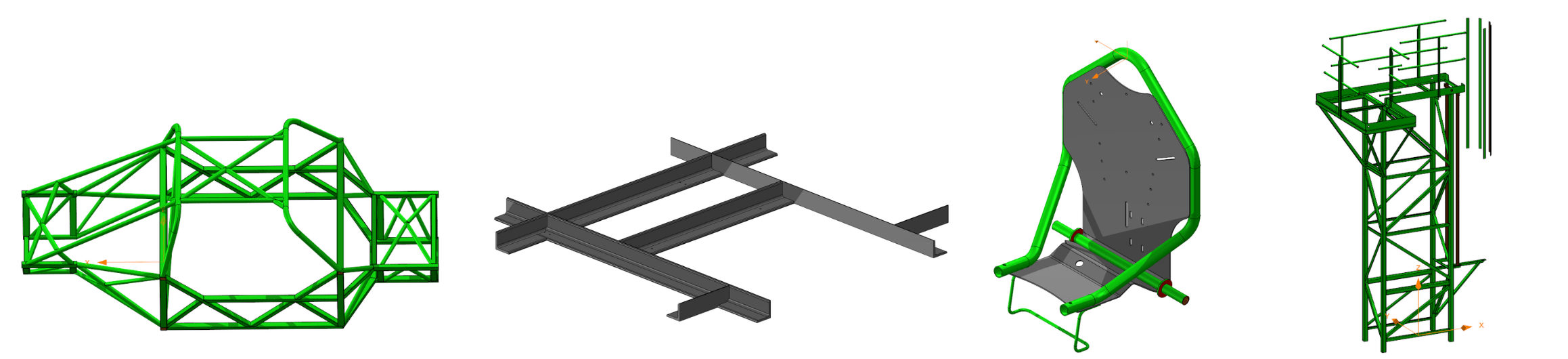
The CAD/CAM software must therefore be able to recognize sections, analyze part geometry and prepare the operations required for cutting, even when the input data varies from one job to another.
Tube nesting involves more than positioning parts
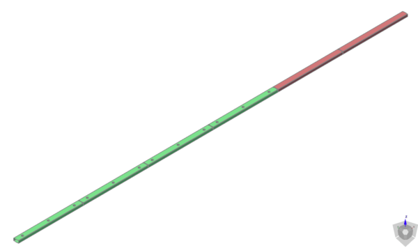
Before cutting, tube nesting determines how parts are arranged across the available bars to use material efficiently. Material utilization is one objective, but the nesting layout must also respect the constraints of the cutting process and the machine.
An efficient nesting layout therefore has to consider several criteria at the same time. For the same parts and stock, different nesting algorithms can produce significantly different results.
What determines the quality of an optimized nesting? Explore the principles behind tube nesting optimization.
Why does machine kinematics matter in tube cutting?
A tube cutting machine has many moving components: rotary and linear axes, mandrels, supports, loading and unloading systems, and more. Their movements must be coordinated throughout the cutting process. Machine kinematics directly affects cutting quality, productivity and machine safety.
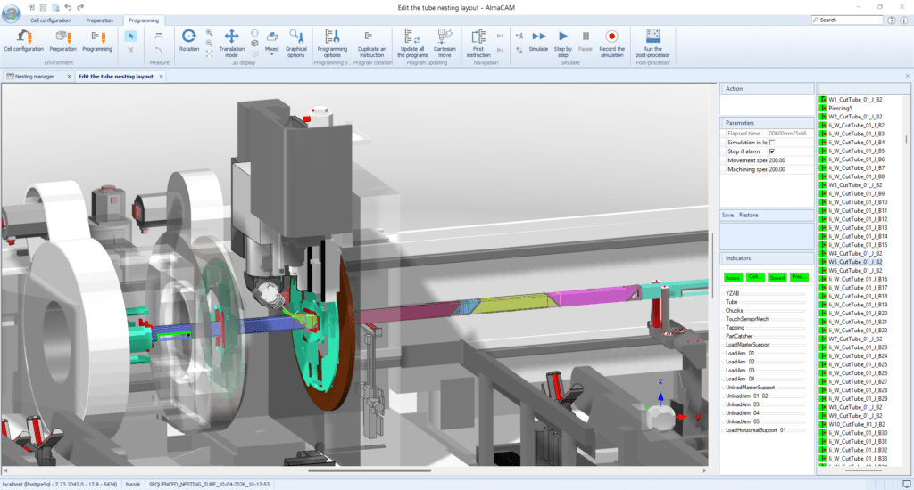
Long parts introduce additional constraints. The material must remain stable throughout the process, including when the final cut releases the finished part.
An NC program may therefore be theoretically correct but impossible to run properly if the machine’s actual movements and constraints have not been taken into account.
Programming is not just about defining where the cutting head should cut. The software also has to determine how the machine will position and move its different components to perform each operation efficiently and safely.
Why is collision avoidance essential in tube cutting?
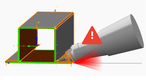
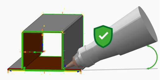
Collisions are a major risk in tube cutting. The cutting head can collide with the tube or profile, but also with clamps, supports, unloading systems or other machine elements. Complex bevel cuts can further increase this risk.
The consequences can be significant: damaged nozzles, interrupted production, scrap parts or, in the most serious cases, machine downtime.
Collision detection should therefore be part of production preparation. Machine simulation have to identify potential risks before production and, when possible, allow toolpaths to be adjusted before the program is sent to the machine.
How does CAD/CAM software handle tube cutting complexity?
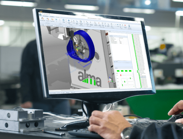
Managing tube cutting complexity means considering the parts, manufacturing constraints and the actual behavior of the machine together. Advanced CAD/CAM software such as Almacam Tube connects these elements throughout the programming process.
It should enable programmers to:
- Handle a wide variety of tubes and profiles, including complex sections and geometries
- Take the machine’s actual kinematics into account, including axes, chucks, supports and other moving components
- Anticipate collisions before production by simulating movements and adjusting toolpaths when necessary
- Automate tube-specific programming operations, such as cutting sequences, lead-ins and lead-outs, and tabs
- Optimize material utilization and production efficiency while considering both part and machine constraints
The main benefit is that all these operations can be managed within the same programming environment, from geometry preparation to the generation of the machine-specific NC program. This is what Almacam Tube is designed for.
Key takeaways about tube cutting complexity
- Tube cutting is more complex than sheet metal cutting because part geometry, machine kinematics and manufacturing constraints interact.
- Tube nesting must combine material optimization with production constraints.
- Machine kinematics directly affects how parts can be cut and programmed.
- Collision detection and machine simulation help identify risks before production.
- Efficient tube cutting requires CAD/CAM software that can manage geometry, nesting, machine kinematics, collisions and programming as a connected process.