Must-have features for an efficient shipbuilding CAD/CAM software
In several important aspects, shipbuilding differs from other industries that construct large structures. Why? What are the specificities of these sectors? To be efficent, what are the capabilities of a good shipbuilding CAD CAM software?
Having worked for more than 40 years with the engineering teams that need CAD and CAM solutions, at Alma, we now know the capabilities that are essential for a shipbuilding project. Read more.
What makes shipbuilding different?
Shipbuilding stands out because ships and offshore structures often begin the engineering process before the design is fully approved, and construction starts before engineering is complete. This requires consideration of pre-existing engineering work and built sections when implementing necessary changes.
Additionally, shipbuilding is governed by specific regulations and regulatory bodies unique to the industry. Unlike large onshore facilities, each ship operates in diverse environmental, regulatory, and political contexts as it travels globally, adding layers of complexity not found in other large-scale construction projects.
In this context, CAD and CAM software are crucial for ensuring an successful shipyard, as they streamline design, enhance precision, and optimize production processes.
A good CAD-CAM software should …
Take into account the way a ship is build
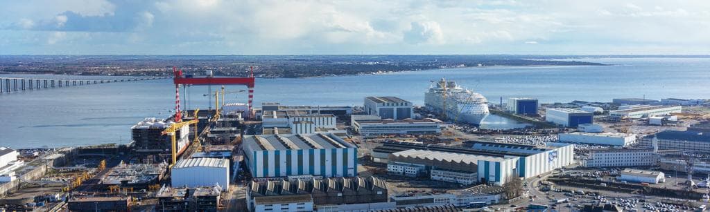
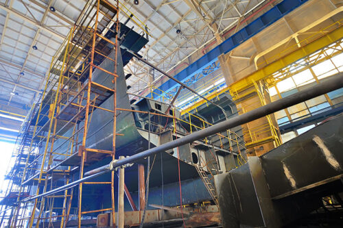
First of all, it is important to understand how ships are built, because that determines the data (parts to cut, stock of sheets and offcuts). A ship is made up of blocks, progressively assembled starting from the middle, to achieve good balance. Each block consists of sub-assemblies, which in turn consist of floors and walls.
That’s why it is usually recommended to organize the data in blocks, to avoid mixing up parts from different blocks in the same nesting layouts. It is important not to complicate the logistics, which are already very demanding, and to simplify sorting of the cut parts so they can be sent to the sub-assemblies where they must be welded.
Similarly, the material needs, which are often calculated before completing the detailed design of the ship, based on the initial versions of the parts resulting from the CAD, will be used to define the stocks of sheets necessary for each block, bearing in mind that recoverable offcuts can sometimes be transferred from one block to another.
Integrate into the shipyard's IT environment
In the naval sector, the CAM solution is the final element in the manufacturing chain, and must therefore communicate with all the information management systems used by the shipyard. This involves importing the geometries of the parts to be cut -which we’ll talk about just after-, but also importing the list of parts to be produced, with their production information (quantity, latest date, etc.), which is often supplied by an MRP or PLM system, independent of the CAD. Similarly, sheet metal stock is often managed by a dedicated MRP with which the CAM software must interface, in order to import nestable sheet metal.
In return, the nesting results (which parts have been cut, from which sheets, what reusable offcuts have been generated) must be exported to inform the MRP or PLM. The NC programs to be cut must also be made available on a workshop workstation, along with a workshop document often customized, containing all relevant information (id of the sheet to be cut, machining time, list of parts cut, etc.), so that the machine operator can launch the cutting program.
Retrieve geometric and machining data
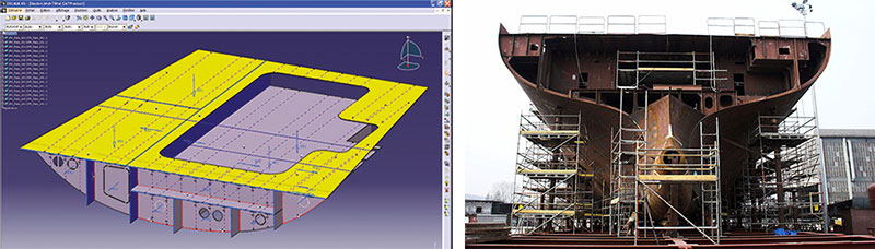
From the very first shipbuilding project, we’ve started by defining a neutral format for data exchange with the CAD tools for an easy integration. Then as time went by, we developed interfaces with every system in the field, so that today we can work with any shipyard no matter which CAD it has chosen to use. We import the geometries describing the parts to cut, if necessary separating them in the case of a multi-part DXF, and we retrieve all the most commonly used machining data.
These data may be the different marking and grinding processes, the wide variety of texts indicating the name of the stiffeners to weld, the ship axes, the folding lines, the chamfer properties applied to each edge, etc. It is worth noting however that when deploying our solution, in addition to importing the geometry and machining characterizing a part, it is almost always necessary to adapt the process for importing and exporting the parts to cut to the shipyard’s operating process. For example, how should part modifications be managed? Is it necessary to systematically invalidate the nesting layouts impacted by a modified part, or is better to allow the user to do so?
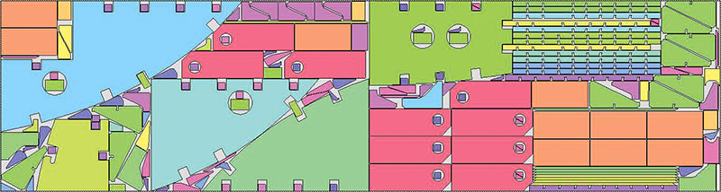
Automate parts nesting and optimized cutting paths
Given the quantity of sheet metal parts that make up a ship, the material savings that the CAM software can bring is the main argument for changing nesting software. Because there are very efficient nesting systems, as the one in Almacam, and bad ones. It’s worth noting that in naval terms, a 1% gain in material use can translate into a saving of several hundred thousand dollars on annual ship production.
A software provider of CAM and nesting solutions should be able to prove you his expertise, and propose you to do a benchmark based on real parts. It’s a factual way for you to see the added value of effective nesting.
At Alma, the development of nesting algorithms has been the primary reason from 1979. Alma’s 30.000 users worldwide are the proof that our nesting algorithms are certainly the best. Today, a dedicated team of engineers is working on this topic, continuoulsy improving algorithms and developing new ones, to further reduce the percentage drop.
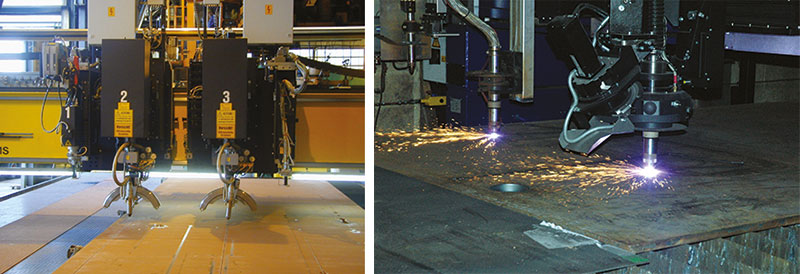
Completely master plasma cutting, cutting of chamfers and marking
Any shipbuilding CAD/CAM solution has to take account of the specificities associated with the industry and the most popular machines. It is therefore particularly vital to master plasma cutting (the most frequently used technique due to the thickness of the sheets to cut).
So among the most frequently used functionalities, we will find continuous cutting (bridged parts to minimize the number of lead-ins and therefore machining time), management of plate straps (leaving certain openings attached to the part for transportation requirements), and cutting of the skeleton (to evacuate it more easily).
In the shipbuilding business it is also necessary to have the capacity to manage machines that produce chamfers, and to manage the associated operations (multi-passes, height verification, reconfiguration loops, etc.) as well as specific marking units. In particular these operations make it possible to trace all kinds of texts which are used for assembling or welding the parts.
Manage (very) special machines
But the biggest contributing factor to our success in shipbuilding is our capability to manage special machines. To do this, you should rely on an open solution, enabling to use the basic functionalities of the CAD/CAM software to develop completely customized applications.
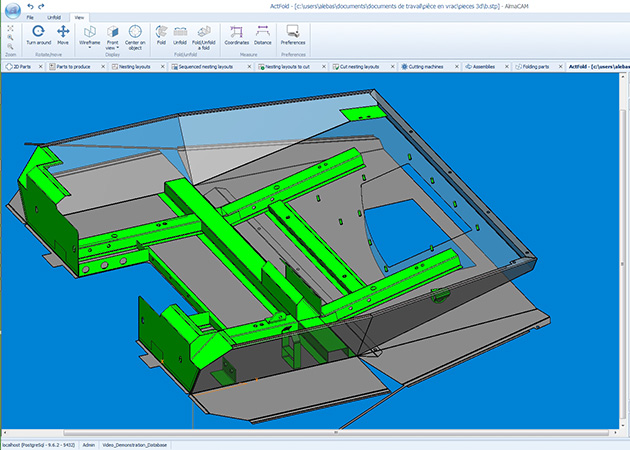
For example, with Almacam, you can manage lines of “flat panel” machines. These machines assemble and weld sheets to then cut out a particularly large part constituting a deck of the ship, and ultimately, weld the sections or stiffeners ensuring it is rigid and perfectly flat. The machine used to carry out cutting can also be used to perform other operations such as grinding, marking, text tracing and chamfering.
Another example of the special machines that Almacam manages, are “symmetrical” machines. Some symmetrical machines can simultaneously mark/cut port and starboard parts that are “virtually” identical. Others are “asynchronous double head” machines that can cut the top and bottom of the same part simultaneously without the cut edges being exactly parallel.
Automate software functioning
Another particularity of shipbuilding is the huge quantity and variety of parts that need to be nested and cut. This enables us to hone our automatic nesting algorithms, and more generally requires their functioning to be as automated as possible: that reduces programming times and risks of error.
As a result, the vast majority of the projects we deploy are structured around the following phases, performed and sequenced automatically:
- Import of parts with preparation of machining,
- Creation of start-up orders (grouping by material/thickness/block),
- Nesting and generation of the NC files in batch mode.
In one last optional phase, the start-up orders are closed in order to declare the cut parts and make available the off-cuts generated by the nesting layouts. It is also important to note that the documents automatically made available to the machine operators and programmers are almost always customized, in particular to meet the need to identify the cut parts and facilitate sorting.
Our range of Almacam software for 2D and 3D cutting and welding perfectly match these requirements specific to shipbuilding.
Manage linear cutting and robotic welding processes
As already mentioned, a ship consists of sheets and sections assembled by welding, in which the main purpose of the sections is to stiffen the ship’s structure. The cables and pipes are positioned in the sub-assemblies or blocks. The interior fittings are installed as early as possible, but after assembly of the first blocks.
In this process, Almacam is deployed not only to nest and cut parts from sheets, but also to optimize cutting of the sections. As a result we have developed various section nesting algorithms to maximize use of the raw material bars, while meeting the requirements imposed by the machines that we manage (saws or robots).
In addition, to complete our know-how, we are exploring welding issues linked specifically to shipbuilding. Almacam Weld software comprises numerous functionalities for automatic geometric recognition of 3D shapes and generation of welding tasks, enabling us to meet the off-line programming needs of welding robots.
What about the team to support you ?
To make your shipyard project suceed, the experts who work with you should have a strong partnership-based approach and the commitment to provide you with a high level service.
Above and beyond the technical capabilities of our CAD-CAM software, Alma’s reputation is the result of skills acquired over the years thanks to trust-based relationships with our customers and solid partnerships with different players in the shipbuilding world, in particular vendors of CAD and PLM solutions.
This expertise has been gradually acquired over a period of 40 years and has been disseminated to all the sales and technical teams in our network. It enables us to tackle any shipbuilding project in the world with confidence and peace of mind. We are fully familiar not only with the general issues raised by shipbuilding, but also with the specificities associated with different types of ships or the location of the shipyard.
We work with the largest European builders of cruise liners, and we provide equipment to many builders of military vessels and cargo transportation ships, right around the world (Brazil, USA, France, Italy, Germany, China, India, Indonesia, Korea, Japan, etc.).
Why is Alma the cutting CAD/CAM market Leader for shipbuilding?
Alma company started to explore the world of shipbuilding in 1982. At that time, the French shipyard at Saint-Nazaire was looking for a way to minimize its material losses. Alma had just developed powerful automatic nesting algorithms. This was the starting point for a sustainable collaboration around the Almacam software. Since then, the CAM tool has continuously been improved and Alma team of experts has aquired solid expertise. Nowaydays, Almacam has become the trustable reference for shipyard.
Minimizing material losses, the 1st aim at the origin of Almacam solution
Alma started to explore the world of shipbuilding in 1982. At that time, the Chantiers de l’Atlantique shipyard at Saint-Nazaire was looking for a solution to minimize its material losses. Bearing in mind the tonnes of steel used to build a cruise liner, this represented savings that would be more than substantial. Alma had just been created, with the aim of promoting to industry the automatic nesting algorithms developed as part of a research project at the University of Grenoble. This was the starting point not only for our long-standing collaboration with the Saint-Nazaire shipyard, but also for development and deployment of our Cutting CAD/CAM software for shipbuilding right around the world. Today this software enables us to meet every specific shipbuilding need, and to be recognized as the major player in shipbuilding CAD/CAM applied to sheet metal working.